This blog post describes the physical characteristics of wireless networks - in particular those of the LoRaWAN technology - in terms of range. The presented information supports the planning process and the evaluation of LoRaWAN use cases.
Part 1 of the article explains the factors and their interrelationships that influence the radio range. Part 2 "Range and coverage of LoRaWAN in practice" shows and evaluates measurement examples from the real environment separately.
In radio technology, there are essentially three properties with which a network can be characterized:
- the range/distance,
- the data transmission speed and
- the energy consumption.
It is difficult to give equal weighting to all three criteria 
WiFi and Bluetooth, for example, achieve very high data rates, but the energy consumption is comparatively high and the range very short. All users of smartphones are only too well aware of this hunger for energy. The base stations of the major telecommunications providers offer high data rates and relatively long ranges, but a large amount of energy must be available for this. This is why the power supply is always a very important planning factor in such installations.
In practice, an optimization to a maximum of 2 of the above mentioned criteria is possible. - So you always have to decide which properties have priority.
The link budget
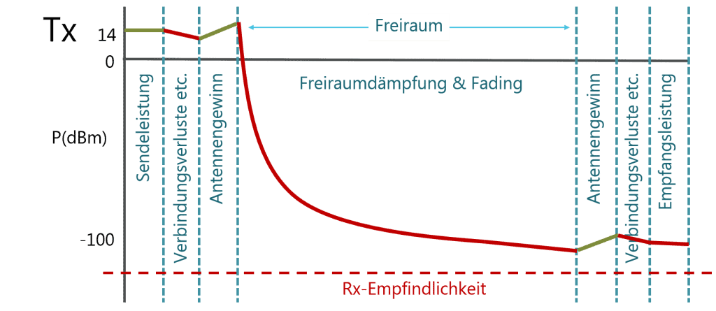
The link budget, (or the so-called power transmission balance) indicates the quality of a radio transmission channel.
Using a simple model, the link budget can be calculated by addingtransmitter power (Tx),receiver sensitivity(Rx), antenna gain andfree space path loss (FSPL).
The link budget of LoRaWAN is then calculated.
LoRaWAN Starter Kit
The path loss
The path loss indicates how much energy is lost in free space over a distance between Tx and Rx. The further the distance between Tx and Rx, the lower the energy. The path loss is usually represented as follows:
FSPL = (4πdf/λ)2 = (λ/c)2 (1)
...means..:
FSPL = Free Space Path Loss
d = distance between Tx and Rx in metres
f = frequency in Hertz
There is also a widely used logarithmic calculation formula for free space damping:
FSPL (dB) = 20log10(d) + 20log10(f) - 147,55 (2)
A doubling of the distance (d) thus means 6dB of loss (in free space).

On the receiver side (Rx), the sensitivity of the receiver is the quantity that influences the link budget. The so-called Rx sensitivity describes the minimum possible receiver power and tolerance for thermal noise and is calculated as follows
Rx sensitivity = -174 + 10log10(BW) + NF + SNR (3)
...means..:
BW = bandwidth in Hz,
NF = noise factor in dB,
SNR =signal to noise ratio. It indicates how far the signal exceeds
...must be the noise.
The Rx sensitivity of LoRaWAN is higher - and therefore better - than e.g. WLAN.
Formula (4) shows the extreme case of path loss without including antenna gain and other types of free space attenuation:
Link Budget = Max. Rx sensitivity (dB) - Max. Tx power (dB) (4)
An example for the calculation of a LoRaWAN link budget:
Tx power = 14 dBm
BW = 125KHz = 10log10(125000) = 51
NF = 6 dB (the gateways in LoRaWAN networks have lower NF values)
SNR = -20 (for SF=12)
These numbers entered in formula (3) give a Rx sensitivity of -137 dBm
Rx sensitivity = - 174 + 51 + 6 - 20 = -137 dBm
The link budget can then be calculated as follows using formula (4):
Link budget = -137dB - 14dB = -151dB
With the specified values, the LoRaWAN link budget is 151 dB.
With the LoRaWAN-specific link budget of 150 dB, a distance of up to 800 km can be covered under optimal conditions (pure free space attenuation). The current LoRaWAN world record is a range of 702 km.
Under real conditions these ideal values are of course not achieved. This depends on several factors.
Free space loss factor
By doubling the distance, the free space attenuation for LoRaWAN increases by 6 dB, thus the attenuation of the radio propagation is subject to a logarithmic function (see formula (1)).
In addition to the loss of energy depending on the distance, factors such as reflections and refractions of radio waves from objects can cause overlapping of radio waves, which can also have a negative effect on the range. (Note: These correlations are explained very well in the video "LoRa crash course" by Thomas Telkamp starting at position 15:41 ).
Structural damping factor

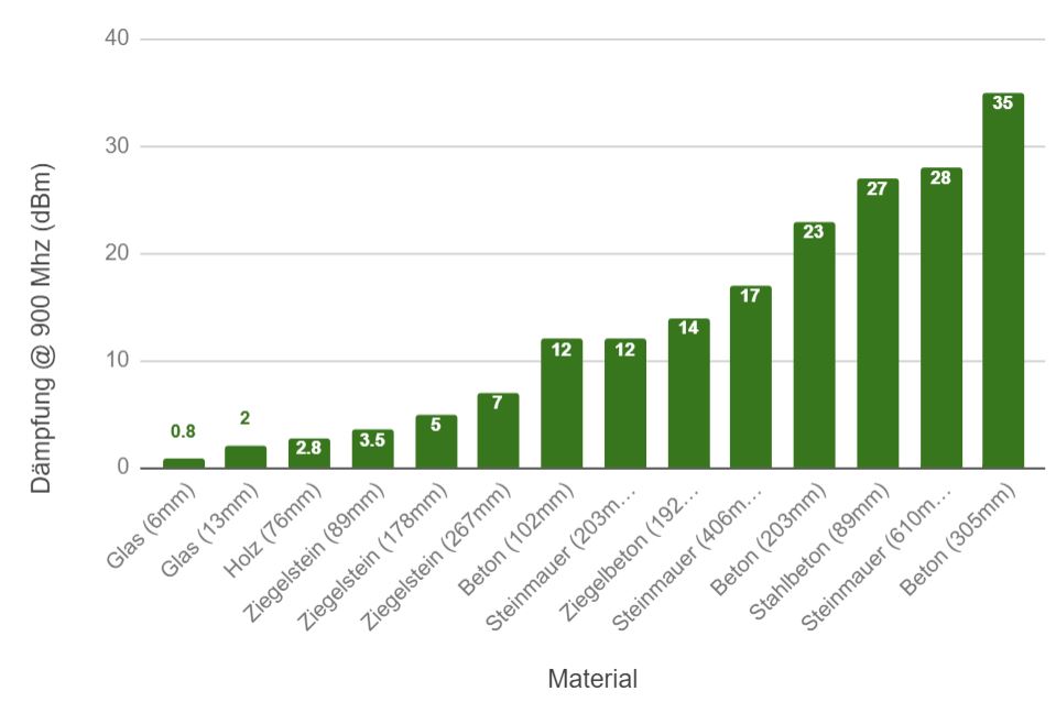
Structural attenuation, i.e. the attenuation of radio signals when they penetrate various obstacles, influences the reception of transmitted signals and significantly shortens the range. Glass, for example, attenuates with just 2dB. This affects the range much less than a thick concrete wall of 30 cm. The table below lists different materials and their typical attenuation.
| Material | Attenuation (dB) |
| Glass (6mm) | 0,8 |
| glass (13mm) | 2 |
| Wood (76mm) | 2,8 |
| Brick (89mm) | 3,5 |
| Brick (178mm) | 5 |
| Brick (267mm) | 7 |
| concrete (102mm) | 12 |
| Stone wall (203mm) | 12 |
| brick concrete (192mm) | 14 |
| stone wall (406mm) | 17 |
| concrete (203mm) | 23 |
| reinforced concrete (89mm) | 27 |
| stone wall (610mm) | 28 |
| concrete (305mm) | 35 |
Fresnel zonefactor
For effective coverage of long ranges and to achieve a good link budget, it is also important to establish a directline of sight between transmitter and receiver as often as possible. In radio transmission, certain spatial areas between the line of sight are called Fresnel zones. If objects are located in these zones, they can have a negative influence on the wave propagation, although there is generally line of sight between the transmitting and receiving antenna. Any object located in the Fresnel zone will lower the signal level and reduce the range (see figure).

Omnidirectional antennas are normally used in LoRaWAN networks. As a result, radiated energy spreads on the horizontal plane where the network nodes and gateways are located. In Europe, the transmission power limit of an ISM band is defined as 14 dBm for a frequency of 868 MHz. Furthermore, the maximum antenna gain is set at 2.15 dBi.
Factor Spreading Factor
A LoRaWAN network uses Spreading Factors(SF) to specifically set the data transfer rate versus range. In LoRaWAN networks SF7 to SF12 are used. LoRaWAN networks are insensitive to interference, multipath propagation and fading (known as fading in electrical engineering) due to their Chirp Spread Spectrum modulation and various phase-shifted frequencies used for chirps. Chirps are used to encode data in LoRaWAN networks on the Tx side, while inverse chirps are used on the Rx side for signal decoding. The SFs mentioned above indicate how many chirps are used per second and define bit rates, per symbol radiated energy and achievable range.
SF9, for example, is 4 times slower than SF7 in terms of bit rates. The scalability of LoRaWAN is achieved by SFs. The slower the bit rate, the higher the energy per data set and the range. LoRaWAN supports an automatic adaptation of the SF factors depending on the network configuration, so-called Adaptive Data Rate(ADR).
Summary
- The link budget defines the maximum range of a LoRaWAN network.
- The free space attenuation reduces the range. Doubling the distance increases the free space attenuation by 6 dB.
- Reflections and refractions of radio waves from obstacles and the ground influence the signal level and range. In the LoRaWAN network, one side of the radio link is usually located near the ground.
- Obstacles in the first Fresnel zone influence the signal level on the Rx side and shorten the range.
- SF values and thus the range of a transmitter depend on the propagation conditions. LoRaWAN allows automatic network management by means of ADR and thus controls the ranges of the transmitters.
- The Rx sensitivity depends on the signal-to-noise ratio (SNR), noise factor (NF) and bandwidth (BW).
LoRaWAN Starter Kit
Strategies for Range of Coverage Optimization at LoRaWAN
The following points must be considered to improve the range in a network with LoRaWAN technology:
- Gateway location: Establish optical visibility between the Tx and Rx antennas. Increase the height of the antennas to achieve optical visibility between the antennas. Using outdoor antennas is always better than using them indoors.
- Choice of antenna: Classical rod antennas concentrate the energy in the horizontal plane. Avoid obstacles in the immediate vicinity of the antenna. Also, it is always better to place them on a mast than on the side of the building. The range should improve if the antenna is carefully selected and the antenna polarization and the maximum defined antenna gain are optimally adjusted to each other.
- Choice of connection material: Use quality connectors (N-type connectors) and cable (LMR 400 or equivalent, with a loss of less than 1.5 dB per 100 m). To reduce the loss in the connection material, it is also important to keep the length of the connection between the station and antennas as short as possible.
- Installation in the vicinity of other radio equipment: Avoid strong interference, for example from surrounding GSM or UMTS stations. Please refer to the manufacturer's operating instructions (usually found under the term "co-localization").
- In general, it should be briefly mentioned in this context that the installation of a LoRaWAN gateway should be accompanied by sufficient surge and lightning protection.

This is the first of two article parts. Part 2 deals with real transmission distances in different urban scenarios.


